Are you wondering how gear pressure angles can transform your mechanical designs? Choosing the right pressure angle is critical for creating gears that perform flawlessly and last longer.
As a CNC machining expert, I’ve seen firsthand how gear design decisions impact everything from automotive transmissions to aerospace systems. That’s why I’m sharing this comprehensive guide packed with practical insights and industry know-how.
In this article, you’ll discover what gear pressure angles are, why they matter, and how to optimize them for your next project. From standard angles like 20° to advanced CNC machining tips, we’ve got you covered.
Let’s dive in and unlock the secrets to precision gear production!
Understanding Gear Pressure Angles Definition and Basic Concept
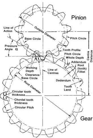
If you’re new to gears, you might wonder, what exactly is a gear pressure angle? Simply put, it’s the angle between the line of action—the path where the force between gear teeth is transmitted—and the tangent to the pitch circle, which is an imaginary circle that represents where two gears effectively mesh.
This angle is crucial because it directly affects how forces move through the gears. A proper gear pressure angle ensures smooth force transmission, reducing wear and improving gear life. Think of it as the direction your push takes when you turn a gear tooth against its mate—the right angle makes sure that push transfers efficiently without causing excessive stress or noise.
In short, the gear pressure angle is a fundamental gear design concept that controls how teeth interact and how power flows between gears, impacting everything from strength to efficiency in your gear setup.
Types of Gear Pressure Angles

When talking about gear pressure angles, it helps to know the main types: normal, transverse, and axial pressure angles. Each one relates to how the forces are angled during gear operation.
-
Normal Pressure Angle
This angle is measured perpendicular to the gear tooth surface. It’s especially important in helical gears where teeth are angled, affecting how the force transfers between the gears.
-
Transverse Pressure Angle
This is the angle measured in the gear’s rotational plane, basically the side view of the gear teeth. It’s the most common reference when designing spur gears.
-
Axial Pressure Angle
Measured along the gear’s axis, this angle matters in helical and worm gears. It helps in understanding forces that try to push the gears sideways along their shafts.
Working Pressure Angle in Real World Applications
The working pressure angle is what gears actually experience during operation, not just a design number. It can vary slightly due to load, speed, and manufacturing tolerances. Getting this angle right is key to smooth power transmission and reducing wear.
In everyday gear design and CNC gear machining, knowing these pressure angle types helps ensure the gears mesh properly, perform well, and last longer—especially for industries like automotive or industrial machinery where precision matters.
Understanding Gear Pressure Angles Common Standards 14.5 20 25
When it comes to gear pressure angles, three common standards stand out: 14.5°, 20°, and 25°. These angles have been shaped by both history and modern engineering needs.
-
14.5° Pressure Angle: This is one of the oldest standards used mainly in older machinery. It offers smoother operation but results in weaker gear teeth that are more prone to wear and damage.
-
20° Pressure Angle: Today, the 20° angle is the industry favorite and the most widely used. It strikes a good balance between strength, durability, and smooth power transmission. This standard is strongly backed by organizations like the American Gear Manufacturers Association (AGMA), which sets benchmarks for gear design and manufacturing quality.
-
25° Pressure Angle: This higher angle offers stronger, more robust teeth, making it ideal for heavy-duty applications where strength matters more than noise or friction. However, it can mean a bit more vibration and wear under normal operating conditions.
AGMA standards help manufacturers in the U.S. and worldwide ensure their gears meet these pressure angle norms for optimal performance. Understanding and choosing the right pressure angle according to these standards is key when designing or buying gears for automotive, aerospace, or industrial uses.
Importance of Pressure Angles in Gear Design Impact on Gear Performance
The gear pressure angle plays a key role in how well gears perform. It directly affects contact stress, durability, power transmission efficiency, and how smoothly and quietly the gears run.
Contact Stress and Durability
A proper pressure angle helps distribute forces evenly across gear teeth. This lowers contact stress, which means less wear and longer gear life. If the pressure angle is off, teeth can wear faster or even break under heavy loads.
Power Transmission Efficiency
The right pressure angle ensures forces transfer smoothly from one gear to another, boosting power efficiency. When gears mesh well, less energy is lost to friction or slippage, which is especially important in automotive and industrial machinery.
Smoothness and Noise Reduction
Gears with optimized pressure angles engage more smoothly. This reduces vibration and noise during operation—a big plus in applications like transmissions and aerospace where quiet performance matters.
Getting your gear’s pressure angle right is crucial. It influences strength, efficiency, and quiet operation, all of which add up to better, longer-lasting gear performance.
Trade Offs of Different Pressure Angles

When it comes to gear pressure angles, there’s no one-size-fits-all answer. Choosing between a low or high pressure angle means balancing efficiency, strength, and durability.
Low Angles (14.5°)
- Higher efficiency: Less friction during meshing means smoother power transmission.
- Weaker teeth: The teeth are thinner, making them more prone to wear or damage under heavy loads.
- Less noise: These gears tend to run quieter, which is great for applications where noise matters.
High Angles (20° and 25°)
- Stronger teeth: Thicker and more robust teeth can handle heavier loads and resist breaking.
- More wear: The increased force on the teeth can cause faster wear if not properly maintained.
- More noise and vibration: Higher pressure angles can make gears noisier during operation.
In practice, industries like automotive and heavy machinery often prefer the 20° angle as a balanced choice, while specialty gear sets might use 14.5° or 25° depending on the design priorities. Understanding these trade-offs helps you pick the right pressure angle to meet both performance and lifespan goals.
Importance of Pressure Angles in Gear Design Applications Across Industries
Gear pressure angles play a big role in different industries, shaping how gears perform based on specific needs.
Automotive
In car transmissions, pressure angles affect how smoothly power moves from the engine to the wheels. Choosing the right angle helps balance strength and efficiency, ensuring gears handle high speeds and torque without squeaking or wearing out quickly.
Aerospace
For lightweight gears in airplanes and drones, pressure angles are selected to reduce weight while maintaining strength. A proper angle here means gears stay reliable under stress without adding extra bulk, crucial for fuel efficiency and safety.
Industrial Machinery
Heavy-duty machines, like those used in construction or manufacturing, demand gears with pressure angles that boost tooth strength and durability. Higher angles are preferred because they resist wear and handle heavy loads, keeping equipment running longer with less downtime.
Across these industries, understanding and optimizing gear pressure angles makes a clear difference in performance, reliability, and lifespan—key factors for US companies aiming for quality and cost-effectiveness.
How to Calculate Gear Pressure Angles Key Formulas and Measurements
Calculating gear pressure angles starts with understanding some key measurements: base pitch and diametrical pitch.
-
Base Pitch is the distance between corresponding points on adjacent gear teeth, measured along the base circle. It’s crucial because it’s directly linked to how teeth mesh and transfer force.
-
Diametrical Pitch is the number of teeth per inch of pitch diameter. This helps define the size and spacing of teeth and is a common standard in the U.S. gear industry.
To calculate the pressure angle, you often use the relationship between the base circle diameter and the pitch circle diameter. The pressure angle (φ) can be found using this formula:
[
\phi = \arccos \left( \frac{\text{Base Circle Diameter}}{\text{Pitch Circle Diameter}} \right)
]
This angle tells you how the forces act along the tooth profile during gear operation.
Relationship with Helix Angle in Helical Gears
In helical gears, things get a bit more complex due to the helix angle—the angle at which teeth are cut relative to the gear axis.
- The normal pressure angle is the pressure angle measured in the plane perpendicular to the helix angle.
- The transverse pressure angle changes based on the helix angle and is calculated using the formula:
[
\text{Transverse Pressure Angle} = \arctan \left( \frac{\tan(\text{Normal Pressure Angle})}{\cos(\text{Helix Angle})} \right)
]
This relationship is vital when designing or analyzing helical gears, especially in CNC gear machining, to ensure efficient force transmission and minimize contact stress.
By mastering these formulas and measurements, you get a solid base for precise pressure angle calculations, essential for optimizing gear performance and durability.
How to Calculate Gear Pressure Angles Tools and Software for Accurate Calculations
When it comes to calculating gear pressure angles, using the right tools can make all the difference in accuracy and efficiency. For precise calculations, software like KISSsoft and ANSYS are industry favorites. These platforms help you analyze the gear geometry, contact stresses, and performance under load, giving you clear insight into the correct pressure angle for your design.
If you’re working on helical gears or complex profiles, these software tools also consider factors like helix angle and load distribution, making them ideal for advanced gear design.
Manual Measurement Techniques
Sometimes, you might need to measure pressure angles without high-end software. In those cases, tools like a vernier caliper come in handy. Here’s how:
- Measure the base pitch and the diametrical pitch of the gear teeth.
- Use these measurements alongside simple formulas to estimate the pressure angle.
- Compare the line of action and pitch circle tangent using basic instruments.
While manual methods won’t be as precise as software, they are useful for quick checks or when access to digital tools is limited.
Using both software and manual techniques ensures you cover all bases for accurate pressure angle calculations in gear design.
How to Calculate Gear Pressure Angles Common Challenges and How to Overcome Them
Calculating gear pressure angles might sound straightforward, but it comes with some real challenges. Here’s what often trips people up and how to tackle those issues:
-
Accurate Measurement of Base Pitch
Getting the base pitch right is crucial. Minor errors here lead to wrong pressure angle values. Use precise tools like a Vernier caliper or specialized gear measuring devices to improve accuracy.
-
Dealing with Helical Gears
Helical gears add a layer of complexity. The helix angle affects the pressure angle calculation, so you need to adjust calculations to account for that. When in doubt, rely on software designed for helical gear analysis.
-
Misinterpreting Gear Standards
Different industries and gear types might use different standards (like AGMA). Make sure you know which standard applies to your project to avoid mismatches.
-
Manual Calculation Errors
Manual formulas can be tricky, especially when converting units or handling complex gear geometry. Double-check calculations or use trusted calculation software like KISSsoft or ANSYS to minimize errors.
-
Surface Wear and Damage
Worn or damaged gear teeth can throw off measurements. Inspect gears before measuring and consider using new or lightly used gears for accuracy.
Tips to Overcome These Challenges:
- Always use the right tools for measuring gear dimensions.
- Leverage gear design software to automatically handle complex calculations.
- Understand the specific gear type and industry standards before starting calculations.
- Perform multiple measurements and average results when doing manual calculations.
- When possible, consult a gear expert or experienced machinist for tricky cases.
Staying aware of these challenges and addressing them head-on helps ensure your pressure angle calculations are spot on and your gears perform reliably in real-world applications.
Optimizing Gear Pressure Angles in CNC Machining Selecting the Right Pressure Angle for Your Project Load Speed and Material Considerations Balancing Cost and Performance
When you’re optimizing gear pressure angles for CNC machining, choosing the right angle is crucial. It all comes down to the specific needs of your project — like the load the gear will handle, the speed it will run at, and the material you’re using.
Load and Speed Matter
- High load, low speed: A larger pressure angle (like 20° or 25°) can handle more force, making gears stronger and more durable under heavy stress.
- Low load, high speed: Smaller angles (like 14.5°) reduce friction and improve efficiency, helping gears run smoother and quieter at fast speeds.
Material Considerations
- Different materials respond differently under stress. For example:
- Steel gears do well with higher pressure angles since they can absorb more force without damage.
- Plastic or lightweight materials might benefit from smaller pressure angles to reduce wear and tear.
Balancing Cost and Performance
- Higher pressure angles often mean stronger but more complex gear teeth — which can increase manufacturing costs.
- Lower pressure angles might be cheaper but can sacrifice durability.
- The goal is to find that sweet spot where you get reliable performance without blowing your budget.
In short, understanding the load, speed, and materials involved helps you pick a pressure angle that balances strength, smoothness, and cost — critical for CNC gear machining projects aiming for quality and efficiency.
Optimizing Gear Pressure Angles in CNC Machining
Role of Precision CNC Machining
Precision is king when it comes to CNC gear machining. Getting the pressure angle just right means every gear tooth meshes smoothly, reducing wear and boosting gear life. CNC machines deliver tight tolerances that manual methods can’t match, which is critical for complex gears and maintaining consistent pressure angles.
How TOPCNCPRO Ensures High Quality Gear Production
At TOPCNCPRO, quality isn’t a buzzword—it’s the foundation. They use advanced CNC systems to produce gears with exakt pressure angles specified by your project needs. This attention to detail ensures gears handle load efficiently without unnecessary noise or stress points, perfect for U.S. customers who demand reliability in automotive, aerospace, or industrial applications.
Advanced Techniques 5 Axis Machining
TOPCNCPRO leverages 5-axis CNC machining to optimize gear profiles more precisely than traditional 3-axis machines. This lets them machine complex helical gears and adjust the helix angle, which interacts closely with pressure angles. The result is gears with enhanced contact stress distribution, smoother operation, and extended durability—all key factors for high-performance gear sets in demanding industries.
Optimizing Gear Pressure Angles in CNC Machining Profile Modifications and Longevity
When it comes to optimizing gear pressure angles in CNC machining, profile modifications like tip relief and root relief play a key role. These small adjustments help reduce stress concentrations on the gear teeth, which in turn boosts durability and smooths out operation. By carefully adjusting the tooth profile, TOPCNCPRO minimizes contact stress that can cause wear or even tooth failure over time.
Here’s how profile modifications make a difference:
- Tip relief slightly reduces the tooth thickness at the tip, preventing early contact and reducing impact stress.
- Root relief removes sharp edges near the tooth base, lowering the chance of cracks from bending stress.
TOPCNCPRO’s approach combines these modifications with precision CNC machining, delivering gears that not only meet exact pressure angle specs but also last longer under heavy use. This strategy has helped clients in automotive and industrial sectors improve power transmission efficiency while cutting down on maintenance.
In short, optimizing gear pressure angles with profile modifications is a proven way to extend gear life and enhance performance — and TOPCNCPRO is leading the way with tailored CNC solutions that keep your gears running strong.
Common Mistakes and Troubleshooting Mismatched Pressure Angles in Gear Pairs
One of the most common slip-ups in gear design and manufacturing is pairing gears with mismatched pressure angles. When the pressure angles don’t line up, you can expect problems like uneven load distribution, increased wear, and premature gear failure. This misalignment causes the gear teeth to engage improperly, leading to noisy operation and reduced power transmission efficiency.
Here’s what usually happens with mismatched gear pressure angles:
- Poor meshing – Teeth don’t fit smoothly, causing vibration and chatter.
- Higher contact stress – Unequal force distribution wears down teeth faster.
- Increased noise and heat – The friction and rough contact generate excess noise and heat.
- Shortened gear life – Premature failure due to stress concentration and material fatigue.
To avoid these issues, always:
- Check pressure angle specs before pairing gears.
- Use compatible standards like AGMA for pressure angle consistency.
- Measure pressure angles accurately using tools or software.
- Confirm gear teeth profiles match, especially in CNC gear machining setups.
At TOPCNCPRO, we emphasize tight control over pressure angle matching to ensure smooth gear performance and longer operational life. When pressure angles are aligned, you get quieter, more durable gearing that handles power efficiently—exactly what industries from automotive to industrial machinery expect.
Common Mistakes and Troubleshooting Undercutting and Tooth Weakness
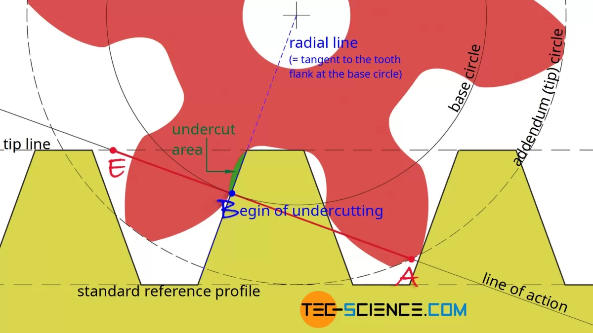
One of the most common issues in gear manufacturing is undercutting, which can lead to tooth weakness. Undercutting happens when the gear tooth profile is cut too deeply near the base, removing material that’s essential for strength. This results in thinner, weaker teeth that are more likely to break or wear out quickly under load.
Here’s what often causes undercutting and tooth weakness:
- Using a pressure angle that’s too low for the gear size or application, which can increase the risk of undercutting.
- Incorrect tooling or improper setup during CNC gear machining.
- Errors in calculating the gear pressure angle or base pitch.
- Trying to make very small gears without accounting for the minimum tooth thickness needed.
To avoid undercutting and tooth weakness:
- Double-check your pressure angle calculations and confirm the right standard fits your gear design.
- Use precision CNC machines capable of maintaining tight tolerances.
- Consult gear design fundamentals, focusing on how tooth shape affects strength and durability.
- Perform routine inspections and measurements during production with tools like vernier calipers or gear inspection software.
Fixing undercut teeth often means redesigning the gear or adjusting the pressure angle. At TOPCNCPRO, we help our customers avoid these pitfalls by applying advanced CNC techniques and thorough quality checks to ensure strong, reliable gears built to last.
Common Mistakes and Troubleshooting
Tips for Avoiding Manufacturing Errors with TOPCNCPRO
Manufacturing gears with the right pressure angle can be tricky. At TOPCNCPRO, we’ve seen common errors that can impact gear quality and performance. Here’s how to avoid them:
- Double-check pressure angle specs early: Confirm the pressure angle before machining starts. A mismatch here leads to poor gear meshing and faster wear.
- Use precision CNC machining: TOPCNCPRO’s advanced CNC equipment reduces tolerance errors, ensuring each tooth matches design specs perfectly.
- Regularly calibrate tools: Keeping calipers, micrometers, and CNC machines calibrated helps avoid subtle mistakes in gear tooth angles and measurements.
- Leverage modeling and simulation: TOPCNCPRO uses software to simulate gear operation, catching potential errors like undercutting or incorrect pressure angles before production.
- Apply profile modifications carefully: We customize tip relief and root relief thoughtfully to reduce stress and extend gear life without compromising strength.
- Communicate clearly with the production team: Clear, detailed drawings and feedback loops prevent misunderstandings that cause manufacturing defects.
By following these tips and relying on TOPCNCPRO’s expertise and tools, you can avoid costly gear manufacturing errors and get reliable, long-lasting gears designed for the U.S. industrial market.
Future Trends in Gear Pressure Angle Design
Advances in Materials and Coatings
One big trend shaping gear pressure angles is the improvement in materials and coatings. Stronger materials like advanced alloys and composites mean gears can handle more stress without needing super high pressure angles for extra strength. This opens up room for optimizing efficiency and reducing wear.
New coating technologies also play a crucial role. Coatings that reduce friction and increase surface hardness help gears last longer and run smoother. These advancements let manufacturers pick pressure angles that balance strength and durability better than ever.
Here’s what you should know about these advances:
- Stronger alloys and composites reduce the need for bulky, strong teeth tied to high pressure angles.
- Low-friction coatings cut down wear and heat, boosting gear life and performance.
- Surface treatments like nitriding improve fatigue resistance, making gears tougher without changing the pressure angle.
In short, better materials and coatings are changing how we think about gear pressure angles—allowing gears to be both stronger and more efficient. For manufacturers in the U.S., this means more options to meet industry demands from automotive to aerospace, balancing cost and durability with smarter gear design.
Future Trends in Gear Pressure Angle Design Impact of AI and Simulation Tools
AI and advanced simulation tools are changing how we approach gear pressure angle design. These technologies let us analyze gear behavior under different conditions more accurately and faster than ever before.
With AI-powered software, engineers can:
- Predict gear contact stress and wear before production
- Optimize pressure angles for specific materials and loads
- Simulate real-world performance including noise and efficiency factors
Simulation tools like finite element analysis (FEA) also help visualize how changes in pressure angles affect gear tooth strength and durability. This means fewer physical prototypes and quicker adjustments during CNC gear machining.
For U.S. manufacturers focused on precision gear production, using AI and simulation reduces errors, cuts costs, and improves product longevity. These tools enable smarter design decisions, helping meet industry standards like AGMA while keeping up with rising performance demands.
In short, AI and simulation are helping push gear design beyond traditional limits, making optimized gear pressure angles accessible and reliable for today’s high-performance applications.
Future Trends in Gear Pressure Angle Design Sustainability in Gear Manufacturing
Sustainability is becoming a major focus in gear manufacturing, including how gear pressure angles are designed and optimized. Manufacturers in the U.S. are pushing to reduce waste, lower energy use, and extend gear lifespan — all while keeping performance top-notch.
Here’s how sustainability is shaping gear pressure angle design:
- Longer-lasting gears: Choosing the right pressure angle helps reduce wear and contact stress, which means gears need less frequent replacement. This cuts down on manufacturing demand and material use.
- Eco-friendly materials: New coatings and lightweight alloys paired with optimized pressure angles reduce energy consumption during operation and production.
- Energy-efficient machining: Precision CNC gear machining methods lower scrap rates and minimize excess material removal, closely tied to how pressure angles are cut and maintained.
- Recycling and reuse: Designing gears with standardized pressure angles helps with refurbishing and recycling parts, reducing landfill waste.
- Carbon footprint reduction: Efficient gear designs with ideal pressure angles improve power transmission, decreasing fuel costs in automotive and aerospace sectors.
By adopting sustainable practices in gear pressure angle design, manufacturers support greener production while delivering reliable, durable gears for U.S. industries. This balance between performance and eco-consciousness is key to the future of gear technology.