Struggling to grasp concentricity and coaxiality in your manufacturing projects? These GD&T tolerances are crucial for precision in parts like gears and shafts, but their nuances can confuse even experienced engineers. At TOPCNCPRO, we’ve distilled years of CNC machining expertise into this concise guide to demystify concentricity and coaxiality. You’ll uncover clear definitions, practical applications, and expert tips to boost your part quality. Ready to master these tolerances? Let’s dive in!
What is Concentricity in GD&T
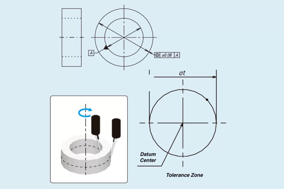
Concentricity in Geometric Dimensioning and Tolerancing (GD&T) is all about controlling the median points of a cylindrical or spherical feature to ensure they align precisely with a datum axis. Think of it as making sure the center points of these features stay perfectly centered around a reference axis, which helps maintain balance and function in the finished part.
Key Characteristics of Concentricity
- It defines a 3D tolerance zone focused on the median points of the feature rather than the entire surface.
- Unlike simple diameter or positional tolerances, concentricity controls how the center points track along the length of a cylinder or throughout a sphere.
- The tolerance zone is a cylindrical area around the datum axis where all the median points of the feature must lie.
Common Applications
You’ll typically find concentricity used in parts where the centerline relationship is critical for performance, such as:
- Transmission gears where the gear teeth need balanced rotation
- Ball bearings to ensure smooth motion and reduce wear
Why Concentricity Is Complex to Measure
Measuring concentricity isn’t straightforward. It requires tracking the center points along a feature’s axis, which is tricky because it involves evaluating median points in 3D space rather than just surface points. This complexity often leads to challenges in inspection, requiring specialized equipment like Coordinate Measuring Machines (CMMs) and careful setup.
Changes in Standards
Note that concentricity was removed from the ASME Y14.5 standard in 2018 due to these measurement challenges and its limited practical application in many cases. Nevertheless, it remains present in older standards and some industry practices, meaning you might still encounter concentricity requirements depending on your project’s documentation or legacy designs.
What is Coaxiality in GD&T
Coaxiality in GD&T refers to the alignment of the axes of two or more cylindrical features with a common datum axis. Unlike concentricity, which controls the median points of a feature, coaxiality focuses purely on the straightness and alignment of the entire axis. This ensures that the shafts or holes stay centered along the same line, which is critical for parts that rotate or fit together tightly.
Key characteristics of coaxiality include its emphasis on axis alignment over just center points. It controls the geometric relationship between the axes of different cylindrical features, helping prevent misalignment that can cause wear or vibration.
Coaxiality is commonly used in parts like drive shafts, hinge pins, and other rotating components where precise axis alignment is essential to performance.
When comparing coaxiality to concentricity, it’s important to note the differences highlighted by ISO and ASME standards. ISO generally emphasizes axis alignment under coaxiality, while ASME in older versions treated concentricity similarly. However, with updates over time, ASME has moved away from using concentricity in favor of more straightforward controls like coaxiality for axis-related tolerances. This distinction helps designers choose the correct tolerance based on the specific functional needs of their parts.
Concentricity vs Coaxiality Key Differences
Understanding the differences between concentricity and coaxiality is vital in GD&T to choose the right tolerance for your parts. Here’s a quick comparison table to break it down:
| Aspect | Concentricity | Coaxiality |
|---|---|---|
| Symbol | ⌭ (Concentricity symbol) | ⌖ (Coaxiality symbol) |
| Tolerance Zone | 3D zone controlling center points | Cylindrical zone controlling axis |
| Measurement Focus | Median points of features’ centers | Axes alignment of cylindrical features |
| Common Use Cases | Ball bearings, washers | Stepped shafts, drive shafts |
| Main Goal | Ensuring center points line up | Making sure axes are perfectly aligned |
| Standards Note | Older ASME Y14.5 includes it | ISO and newer ASME standards prefer coaxiality |
When to Use Each Tolerance
- Use concentricity when the exact location of feature centers matters more than straightness of the axis—like in washers or ball bearings where center balance is critical.
- Pick coaxiality when axis alignment affects function—common in shafts and hinges where rotating parts must run smoothly without wobble.
Common Misconceptions
Some think concentricity and coaxiality are interchangeable because both relate to cylindrical features. That’s not true — concentricity controls center points, while coaxiality controls axis alignment. Confusing the two can lead to incorrect inspections or part failures.
Practical Example
- A stepped shaft needs coaxiality to ensure each cylindrical section’s axis is perfectly aligned; this avoids vibrations during rotation.
- A washer, on the other hand, needs concentricity to make sure the hole is centered within the outer diameter for proper fit.
Getting the right tolerance saves time, reduces scrap, and ensures your parts perform as expected—especially in CNC machining precision.
Why Concentricity and Coaxiality Matter in CNC Machining
Concentricity and coaxiality play a big role in how well a part performs, especially in CNC machining. Getting these tolerances right helps reduce vibrations, ensures parts fit together perfectly, and boosts the overall durability of the product. When parts are properly aligned around their axes or center points, machines run smoother and last longer.
In quality control, these tolerances are key for keeping assembly efficient. Parts that meet concentricity and coaxiality standards fit faster and with less rework. This saves time and cuts costs in production.
At TOPCNCPRO, we use advanced CNC techniques to nail these tolerances every time. Our precision machining and measurement tools keep parts within tight limits, ensuring they work as expected in real-world applications.
Ignoring concentricity and coaxiality can lead to serious issues like wobbling and excessive wear. These problems don’t just hurt performance—they can cause early failure and costly downtime. That’s why controlling these tolerances matters for anyone relying on high-quality, reliable parts.
How to Measure Concentricity and Coaxiality
Measuring concentricity and coaxiality accurately is key to keeping your parts within spec. Here’s what we use and how we do it at TOPCNCPRO.
Tools and Methods
- Coordinate Measuring Machine (CMM): This is the go-to tool. It captures 3D data points from your part and calculates how close the center points or axes line up with your datum.
- Dial Gauge for Runout Checks: While dial gauges don’t measure concentricity directly, they help check related parameters like runout that can give clues about alignment.
- Sample Drawing Analysis: Before measuring, we review the engineering drawings thoroughly. Understanding the tolerance zone and datum references ensures accuracy.
Step by Step Measurement Process
For Concentricity:
- Secure the part firmly on the CMM fixture.
- Sweep multiple points along the cylindrical or spherical feature.
- Calculate the median points and compare them to the datum axis.
- Verify the center points fall within the specified 3D tolerance zone.
For Coaxiality:
- Position the part respecting the main datum axis.
- Measure the axes of the involved cylindrical features using the CMM.
- Align the axes and check the variation to confirm they stay within the coaxiality tolerance zone.
- Document axis alignment deviations if any.
Challenges and Best Practices
- Concentricity measurement is tricky because it involves center points, not just surface checks, which makes it sensitive to part setup and CMM programming.
- Datum selection can make or break accuracy—it’s critical to pick the right reference features.
- Regularly calibrate your CMM and verify fixturing to prevent errors.
- Combining runout checks alongside concentricity/coaxiality helps cross-verify part alignment.
TOPCNCPRO Expertise
At TOPCNCPRO, our precision measuring team is experienced in handling these complex GD&T tolerances. We pair advanced CMM tech with deep knowledge of geometric dimensioning and tolerancing standards to deliver spot-on measurements. This means your parts meet specs the first time, reducing rework and boosting assembly efficiency.
If you’re looking for reliable data on concentricity or coaxiality, we’ve got you covered.
Alternatives to Concentricity and Coaxiality
When it comes to controlling how parts fit and function, runout and total runout are simpler and often more practical alternatives to concentricity and coaxiality. These tolerances focus mainly on surface deviations, making them easier to measure and apply in many cases. For example, runout controls the wobble of a surface as it rotates, which is key in things like shafts and wheels.
Positional tolerance is another strong alternative, especially in modern GD&T tolerances. Position focuses on the location of features relative to datums rather than strict axis or median point control. This makes it more flexible and widely preferred for many precision parts because it balances ease of measurement with functionality.
Here’s when to choose each:
- Use runout or total runout when you’re mainly worried about surface imperfections or wobbling during rotation.
- Choose positional tolerance when feature location is critical, but axis alignment isn’t as tightly controlled.
- Lean on concentricity or coaxiality if your part requires tight control over the relationship of centers or axes, like in high-precision rotating components.
Balancing tolerance complexity with functional needs keeps manufacturing efficient and cost-effective. Most shops find runout and positional controls easier to inspect and apply, but concentricity and coaxiality still have their place in specialty cases. Knowing which fits your part’s function helps avoid overkill and keeps your process smooth.
Practical Tips for Implementing Concentricity and Coaxiality
Implementing concentricity and coaxiality tolerances effectively starts with good design and clear communication. Here are some practical tips to keep your parts precise and functional.
Design considerations
- Specify tolerances clearly in your drawings. Make sure the GD&T symbols for concentricity or coaxiality are easy to identify and linked to the correct datum axis.
- Think about the function of the part. Use concentricity for features needing controlled center points and coaxiality when axis alignment is critical.
- Avoid over-tight tolerances that increase costs but don’t add functional value.
Machining strategies
- Use high-quality bar stock. Starting with consistent material reduces variability during machining.
- Choose the right fixtures and lathes. Precision fixtures and properly maintained lathes ensure better alignment and repeatability.
- Implement step-by-step machining processes to gradually approach the desired tolerance without overshooting.
Quality assurance
- Perform regular tolerance checks during and after production. Don’t wait until final inspection to catch issues.
- Use coordinate measuring machines (CMMs) for accurate verification, especially when concentricity is hard to measure by other means.
- Train your team on GD&T concepts to avoid confusion and mistakes.
How TOPCNCPRO supports clients with GD&T compliance
At TOPCNCPRO, we combine advanced CNC machining technology with GD&T expertise to help you meet concentricity and coaxiality tolerances consistently. Our precision measurement tools and experienced team catch potential issues early, saving time and reducing scrap. Whether your project requires complex axis alignment or simple center point control, we provide tailored guidance and high-quality manufacturing to keep your parts within spec.
Common Mistakes and How to Avoid Them
When working with concentricity and coaxiality in GD&T, there are a few common mistakes that can cause headaches down the line:
-
Using concentricity when positional or runout tolerances would do
Sometimes, concentricity is overused even when a simpler tolerance like position or runout would cover the need. This can make measurement and inspection tougher than necessary.
-
Ignoring the importance of datum selection
Picking the right datum axis is critical. If you don’t set your datum correctly, your measurements for concentricity or coaxiality won’t be reliable, leading to assembly problems.
-
Forgetting material condition modifiers like MMC and LMC
Material modifiers directly affect tolerance application and measurement. Skipping these can cause confusion and improper fits in parts.
At TOPCNCPRO, we tackle these issues head-on by:
- Thoroughly reviewing designs to ensure proper tolerance use
- Guiding clients on the best datum setups for accurate measurement
- Applying material condition modifiers rigorously to meet real-world part function
This helps us deliver precise, build-ready parts that perform as expected without unnecessary delays or rework.