Are you struggling to master press fit tolerance for your mechanical assemblies? Getting the right interference fit can make or break the reliability and performance of your parts, whether you’re designing for aerospace, automotive, or medical applications.
As experts in precision CNC machining, we at topcncpro understand the challenges of achieving perfect fits. Drawing from years of industry experience, we’ve crafted this guide to simplify the process and share actionable insights you won’t find in basic tutorials.
In this post, you’ll discover how to calculate press fit tolerances, apply industry standards like ISO 286, and avoid common pitfalls—all with practical tips to ensure your assemblies are secure and cost-effective.
Let’s dive in and unlock the secrets to precision machining success!
Press Fit Tolerance The Basics
Definition and Core Concepts
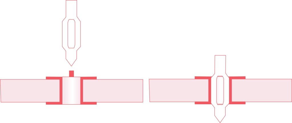
Press fit tolerance refers to the precise dimensional allowance between two mating parts, typically a shaft and a hole, that ensures a secure interference fit without the need for additional fastening. This tolerance controls the interference fit — where the shaft’s diameter is slightly larger than the hole’s diameter, creating a tight fit when assembled.
At its core, press fit tolerance balances between too loose (leading to movement) and too tight (causing difficulty during assembly or potential damage). Properly defined press fit tolerances are essential for reliable mechanical assembly and ensure consistent performance over the product’s life.
Key Terminology
- Interference Fit: A fit where the parts must be forced together due to the shaft being larger than the hole.
- Shaft and Hole Tolerances: The allowable deviations in dimensions for shafts and holes to achieve the desired fit.
- Tolerance Stack-Up: The cumulative effect of various dimensions and their tolerances in an assembly.
- Surface Finish for Press Fits: The surface quality that can impact friction and fit strength during the press fit process.
Understanding these terms is vital for anyone involved with precision machining or designing press fits in CNC operations.
Applications of Press Fit Tolerance
Press fit tolerances are widely used in industries where CNC machining tolerances need to ensure highly reliable joints:
- Automotive components such as engine blocks and gear assemblies
- Aerospace applications requiring vibration-resistant assemblies
- Bearings and shaft assemblies in heavy machinery
- Electrical connectors and housing fits requiring minimal movement
By carefully applying press fit tolerance, manufacturers ensure tight, vibration-resistant, and durable assemblies critical for high-performance products.
If you want to dive deeper into tolerance basics and engineering concepts related to fits, check out this comprehensive resource on engineering tolerance explained.
How to Calculate Press Fit Tolerance with Precision
Calculating press fit tolerance is crucial in getting the perfect interference fit between a shaft and a hole, especially in CNC machining where precision matters. Here’s a straightforward approach to ensure you get tight fits without risking damage or failure.
Step-by-Step Calculation Process for Press Fit Tolerance
-
Identify the Basic Sizes
Start with the nominal diameters of the shaft and hole. These are your base measurements before applying tolerances.
-
Determine Shaft and Hole Tolerances
Use standards like ISO 286 or ANSI B4.1 to get tolerance grades for both shaft and hole. These tolerances define the allowable size variations.
-
Calculate Maximum and Minimum Limits
For both shaft and hole, calculate the maximum material condition (MMC) and least material condition (LMC):
- MMC for shaft: largest shaft diameter
- LMC for hole: smallest hole diameter
-
Find the Interference Range
Press fit requires interference, so subtract the hole’s LMC from the shaft’s MMC to get the maximum interference. Similarly, subtract the hole’s MMC from the shaft’s LMC for minimum interference.
-
Verify the Press Fit Range
The interference values should fall within acceptable limits to avoid too loose or too tight fits which can lead to mechanical failure or assembly issues.
Tools for Accurate Press Fit Calculations
- Press fit calculators are available online and as software plugins. They automate the complex tolerance stack-up calculations and base results on recognized standards.
- CAD software with integrated tolerance analysis modules helps visualize the fits during the design phase.
- Precision measurement tools like micrometers and bore gauges confirm actual sizes during manufacturing and quality checks.
Key Factors Influencing Tolerance Calculations
- Material properties: Different metals expand and contract uniquely, impacting fit after assembly or under temperature changes.
- Surface finish: A rough surface can increase friction, requiring slight adjustments in interference.
- Assembly methods: Press fitting with heat or lubrication changes the effective fit due to expansion or reduced friction.
- Tolerance stack-up: In complex assemblies, accumulated small tolerances can unexpectedly alter the interference, so always consider cumulative effects.
By following this clear process and paying attention to these factors, we can accurately calculate and implement press fit tolerances, ensuring reliable mechanical assemblies in the U.S. manufacturing environment.
Best Practices for Implementing Press Fit Tolerance in CNC Machining
When working with press fit tolerance, getting it right from design through to quality control is key to a smooth mechanical assembly and lasting performance. Here’s how you can nail the process.
Design Considerations for Press Fit Tolerance
- Select the right interference fit type based on the application (light, medium, or heavy interference). This helps avoid overly tight or loose shafts and holes.
- Factor in material properties like elasticity and thermal expansion. Materials like aluminum and steel react differently during assembly.
- Account for surface finish – smoother surfaces reduce friction, affecting how tightly components fit.
- Use standardized shaft and hole tolerances following ISO 286 or ANSI B4.1 to ensure compatibility and avoid guesswork.
- Design for tolerance stack-up especially in complex assemblies to prevent cumulative errors causing fit problems.
Manufacturing Techniques for Precise Press Fit Tolerances
- Utilize precision machining equipment, such as CNC machines calibrated for tight tolerances.
- Consistently monitor and adjust machining parameters to maintain consistent shaft and hole dimensions.
- Employ controlled environmental conditions during machining to reduce material deformation.
- Use a reliable press fit calculator or software to plan fits before production— minimizes trial-and-error.
Quality Control Measures to Assure Fit Accuracy
- Conduct in-process inspections using calibrated measuring tools like micrometers and bore gauges to verify dimensions.
- Perform a trial assembly to test actual interference fit, ensuring no excessive force or gaps.
- Implement statistical process control (SPC) to track variation and quickly spot trends or issues.
- Document all tolerance data and inspection results to build traceability and help with continuous improvement.
By combining these best practices, you’ll reduce the risk of fit failures, save time on corrections, and deliver assemblies that perform reliably—exactly what U.S. manufacturers demand in precision and consistency.
Common Challenges and Solutions in Press Fit Tolerance
When working with press fit tolerance in CNC machining and mechanical assembly, several challenges often arise. Understanding these issues and how to address them is key to achieving reliable interference fits and precision machining results.
Incorrect Interference Causing Loose or Overly Tight Fits
One of the biggest challenges is getting the interference fit just right. If the interference is too low, the fit becomes loose, leading to mechanical play or even part failure. On the flip side, too much interference creates overly tight fits that make assembly difficult, risk cracking, or cause excessive stress on components.
How to solve this:
- Carefully calculate interference using proven standards like ISO 286 and ANSI B4.1, which specify shaft and hole tolerances.
- Use specialized press fit calculators to simulate fits before production.
- Specify proper surface finish for press fits, since rough surfaces can increase friction and affect how tight the fit feels.
- Collaborate closely with manufacturers experienced in precision machining to refine tolerances.
Material Deformation During Assembly
Press fits put stress on components, and materials can deform when the force during assembly exceeds their limits. This deformation leads to parts that don’t meet design specs or can linger as stress points reducing durability.
Mitigation strategies include:
- Choosing suitable materials with the right mechanical properties for press fitting.
- Applying precise manufacturing techniques to control tolerances tightly.
- Using assembly processes like controlled heating or cooling (thermal expansion) to ease fitting without damaging parts.
- Ensuring the tooling and fixtures support parts during assembly to avoid bending or warping.
Tolerance Stack-Up in Complex Assemblies
In assemblies with multiple interfacing parts, the compounded effect of individual part tolerances can cause significant deviations, known as tolerance stack-up. This can lead to misalignment, poor fits, or assembly failures.
To manage tolerance stack-up:
- Model cumulative tolerances early in the design phase.
- Use tighter tolerances on critical components and relax others where possible to balance cost and precision.
- Integrate dimensional inspection at multiple manufacturing stages.
- Collaborate with CNC machining experts who understand stack-up effects and can adjust machining parameters accordingly.
How topcncpro Addresses These Challenges
At topcncpro, we specialize in tackling these common press fit issues through:
- Adherence to recognized industry standards like ISO 286 and ANSI B4.1 to ensure shaft and hole tolerances are spot-on.
- Providing advanced press fit calculators and resources to fine-tune interference fits before machining begins.
- Utilizing cutting-edge CNC machining tolerances and precision tools to limit material deformation and maintain consistent surface finishes.
- Offering expert design consultations to manage tolerance stack-up in complex mechanical assemblies.
- Implementing rigorous quality control measures to ensure every part meets the required press fit specifications.
Our streamlined process and deep understanding of press fit tolerances make us the go-to partner for reliable and precise mechanical assemblies. For more on related tolerance topics, check out our guide on Engineering Tolerance Explained.
Industry Standards and Tools for Press Fit Tolerance
Understanding and applying the right industry standards for press fit tolerance is crucial in achieving reliable mechanical assemblies, especially when working with shaft and hole tolerances in CNC machining. These standards ensure consistency, reduce errors, and help avoid costly rework in precision machining projects.
Overview of Key Industry Standards
Two of the most widely recognized standards in press fit tolerance are:
- ISO 286: This international standard defines the for limits and fits, covering the tolerance ranges for shafts and holes. It’s the go-to for engineers who want to specify interference fits with precision and reliability.
- ANSI B4.1: Mainly used in the United States, this standard sets guidelines for shaft and hole fits as well. It aligns closely with ISO 286 but focuses on U.S. manufacturing practices and materials.
Both standards guide how to calculate and apply interference fits, helping machinists and engineers control CNC machining tolerances for best results.
Useful Tools and Resources
To work confidently with press fit tolerance, you want tools that simplify the calculations and let you check tolerance stack-up quickly:
- Press fit calculators (online or standalone software) that factor in interference amounts and material properties.
- Tolerance chart references based on ISO 286 or ANSI B4.1 for quick selection of fits.
- CAD software plugins that automatically compute fits and generate detailed specs for manufacturing.
- Measurement tools like calipers and micrometers for verifying actual part sizes to ensure they meet tolerance specs.
Using these tools helps avoid common issues like loose fits, excessive force during assembly, or material deformation.
How topcncpro Integrates Standards
At topcncpro, we understand the importance of sticking to industry standards when manufacturing your custom parts. We:
- Apply ISO 286 and ANSI B4.1 standards rigorously to define press fit tolerances for every project.
- Use advanced press fit calculators and CNC software to optimize shaft and hole tolerances before production.
- Perform precision quality control checks that verify actual parts meet the specified surface finish and interference requirements.
- Provide clear documentation and fit recommendations based on industry best practices to support smooth mechanical assembly.
By aligning with these standards and leveraging the right tools, topcncpro ensures your parts fit perfectly every time — no surprises during assembly, no warranty headaches. Our approach saves time, reduces scrap, and improves reliability for your mechanical projects.
Practical Example Applying Press Fit Tolerance in CNC Machining
Case Study Automotive Engine Block Assembly
One of the best ways to understand how to use press fit tolerance is by looking at a practical example in CNC machining—a common scenario is the assembly of an automotive engine block. In this application, press fits are crucial for joining components like camshaft bearings, cylinder liners, and gear shafts securely without additional fasteners.
For instance, the camshaft bearing press fit requires an interference fit with very tight dimensional control to ensure no movement engine operation but still allow assembly without causing part damage. Using the right shaft and hole tolerances guided by ISO 286 standards and ANSI B4.1 can reduce risk of deformation and ensure smooth mechanical assembly.
Visual Aids for Press Fit Tolerances
Visuals play a key role in verifying and communicating the press fit requirements during design and production:
- Dimensional tolerance tables showing nominal sizes and acceptable upper and lower limits.
- Tolerance stack-up diagrams to illustrate the cumulative effect of part-to-part variations.
- Surface finish charts to ensure the mating surfaces have ideal roughness for optimal press fit performance.
- 3D CAD modeling and simulation to predict interference and ease of assembly before production.
These visual tools help engineers and machinists alike confirm the right amount of interference fit is achieved, preventing issues like excessive deformation or loose fits.
topcncpro’s Role in Ensuring Precise Press Fit Tolerances
At topcncpro, we specialize in providing precision machining and custom parts that meet strict press fit tolerance requirements. We use advanced CNC machining technologies combined with our in-house press fit calculator tools to:
- Calculate exact interference values based on material properties and application needs.
- Control manufacturing processes with tight CNC machining tolerances to meet ISO 286 and ANSI B4.1 standards.
- Implement rigorous quality control measures, including dimensional inspection and surface finish verification.
- Provide detailed reports and support to help clients optimize mechanical assembly and avoid fit-related challenges.
Our expertise ensures that your engine block components, or any other critical assemblies, achieve perfect press fits—leading to durable, high-performance parts with consistent assembly outcomes.
For more foundational info on engineering tolerances and practical guidance, check out Engineering Tolerance Explained. This helps bridge the gap between design concepts and the precision required in real-world CNC machining jobs.
This real-world case shows how to detail in press fit tolerance can make a big difference in performance and reliability. With the right calculations, tools, and manufacturing techniques, you get assemblies that hold up under pressure without costly rework or failures.