Are you struggling to grasp True Position in GD&T? Mastering this concept can transform your approach to precision manufacturing and ensure flawless part assemblies.
As a CNC machining expert, I’ve seen firsthand how True Position unlocks tighter tolerances and cost-efficient production. At topcncpro, we leverage this GD&T principle to deliver high-quality parts that meet the toughest standards.
In this guide, you’ll discover what True Position is, how to calculate it, and why it’s a game-changer for CNC machinists and engineers.
Let’s dive in!
GD&T Basics Setting the Foundation for True Position
Before diving into True Position GD&T, it’s important to understand the basics of Geometric Dimensioning and Tolerancing (GD&T). GD&T is a standardized system used to define and communicate engineering tolerances clearly and precisely on technical drawings. It provides a common language for designers, machinists, and quality inspectors to ensure parts fit and function as intended.
Overview of Geometric Dimensioning and Tolerancing GD&T
GD&T uses symbols, feature control frames, and datum references to specify complex geometry requirements. Instead of simply stating size limits like traditional dimensioning, GD&T controls the form, orientation, and location of features within a defined tolerance zone. This approach improves manufacturing flexibility and reduces guesswork.
Key GD&T Components You Need to Know
- Feature Control Frame: This is the heart of GD&T, a rectangular box that describes the tolerance type, value, and datums.
- Datums: Reference points, lines, or planes from which measurements originate.
- Tolerance Zones: The three-dimensional limits within which a feature’s geometry must lie.
- Material Condition Modifiers: Symbols like Maximum Material Condition (MMC) that adjust tolerance depending on part size.
True Position vs Other Location Tolerances
Location tolerances in GD&T help control the exact placement of features like holes, slots, or pins relative to datums. True Position is the most precise location tolerance. Unlike basic positional or coordinate tolerancing methods, True Position defines a cylindrical tolerance zone where the feature’s center must fall. This allows for more realistic, flexible tolerances that account for manufacturing variations while keeping parts interchangeable and functional.
In comparison, other location tolerances may only control in one plane or dimension, but True Position captures the full 3D location accuracy. This makes True Position the go-to method for tight tolerance applications typically seen in CNC machining precision and high-performance parts.
Understanding these GD&T basics sets the stage for mastering True Position. It’s more than just a symbol; it’s a powerful tool to improve manufacturing accuracy, reduce scrap, and enhance product quality. Let’s explore how True Position is defined and calculated next.
Defining True Position Core Concepts in GD&T True Position

Understanding True Position is key to mastering GD&T (Geometric Dimensioning and Tolerancing). It’s one of the most commonly used symbols and controls for ensuring parts fit and function properly, especially in CNC machining and manufacturing.
What is True Position
True Position defines the exact location of a feature, like a hole or a slot, relative to its specified datums. Instead of just specifying where a feature should be, it controls the permissible variation around that location. This makes sure the feature stays within a defined tolerance zone, helping parts assemble correctly.
At its core, True Position manages:
- Location accuracy by limiting how far a feature can shift.
- Allowance for manufacturing imperfections while maintaining function.
- Complex relationships between multiple features based on the datum references.
The True Position Symbol
In GD&T, the True Position symbol looks like a circle with a cross through it (⌀). It appears inside the Feature Control Frame, which lists the tolerance value, any applicable modifiers like Maximum Material Condition (MMC), and the datum references the feature relates to.
This symbol signals that the positional tolerance applies to that particular feature. When you see it, you know the focus is on controlling the feature’s exact spot within a tight cylindrical zone.
Tolerance Zones in True Position
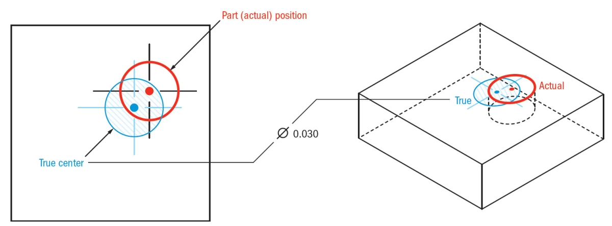
True Position typically uses a cylindrical tolerance zone, which is a 3D space shaped like a cylinder around the exact location of the feature. The center of this cylinder is the “true” or ideal position.
- The feature’s center must lie inside this cylinder.
- The diameter of this cylinder is the allowed positional tolerance.
- Using modifiers like MMC can add bonus tolerance, giving more flexibility during manufacturing without sacrificing assembly quality.
This system keeps holes and other features aligned correctly while accounting for some small variations.
Role of Datums in True Position
Datums act like a frame of reference. They’re real, physical points, lines, or surfaces on a part used to establish an origin for the True Position tolerance.
- Without datums, True Position wouldn’t have a reliable reference point.
- Datums help align parts consistently for inspection and assembly.
- Common datum setups might include a primary flat surface (Datum A), a perpendicular surface (Datum B), and a third datum to completely locate the part in space.
The better the datums are defined and controlled, the more precise the True Position measurement will be, ensuring that manufactured parts work smoothly in their intended assemblies.
Knowing these core concepts about True Position prepares you to both interpret and apply location tolerances effectively. It’s the foundation for maintaining tight controls, boosting production quality, and making sure parts fit as intended.
Calculating True Position Step by Step
Understanding how to calculate True Position is essential when working with GD&T. It ensures that parts fit and function as intended, especially in precise applications like CNC machining. Let’s break down the process with formulas, examples, and a look at bonus tolerances and material conditions.
The True Position Formula and Calculation
True Position defines the allowable deviation from a perfect location for a feature relative to datums. The formula to calculate True Position is:
True Position = 2 × √(ΔX² + ΔY²)
- ΔX = deviation in the X-axis
- ΔY = deviation in the Y-axis
This formula calculates the radial distance between the actual feature center and the theoretical exact position. The multiplication by 2 gives the diameter of the cylindrical tolerance zone within which the feature must lie.
Example Calculation
Say you have a hole whose center is supposed to be at coordinates (50, 75) relative to its datums. After measurement, the hole center is at (49.8, 75.3).
- ΔX = |50 – 49.8| = 0.2
- ΔY = |75 – 75.3| = 0.3
Calculate:
True Position = 2 × √(0.2² + 0.3²)
True Position = 2 × √(0.04 + 0.09)
True Position = 2 × √0.13
True Position ≈ 2 × 0.36 = 0.72 mm
This means the hole center is within a 0.72 mm diameter tolerance zone.
Bonus Tolerance and Material Conditions
Maximum Material Condition (MMC) plays a significant role in True Position calculations. MMC allows extra tolerance — called bonus tolerance — when the actual feature size deviates from its maximum material limit.
- If a hole is larger than its MMC size, the true position tolerance can increase.
- This bonus tolerance helps balance manufacturing variations without compromising part function.
For example:
- Specified True Position tolerance: 0.5 mm
- Hole size actual: 0.02 mm larger than MMC
- Bonus tolerance = 0.02 mm
- Total allowable true position tolerance = 0.5 + 0.02 = 0.52 mm
Using Material Condition modifiers adds flexibility and maximizes part acceptance during inspection.
Tools for True Position Calculation
To accurately calculate and verify True Position, these tools are commonly used in the U.S. manufacturing industry:
- Coordinate Measuring Machine (CMM): Provides precise 3D measurements and directly calculates True Position.
- Optical Comparators: Useful for 2D inspection and measuring deviations visually.
- Calipers and Micrometers: Measure physical dimensions but often require additional calculations for True Position.
- GD&T Software Tools: Many CNC shops use integrated software that automates True Position calculations based on measured data, including bonus tolerance.
Integrating these tools ensures precision across production and inspection, improving reliability in critical parts.
For more on machining precision and handling complex features, you can check out Chamfer 101 understanding chamfers and chamfered edge which complements the GD&T process.
Practical Applications of True Position in CNC Machining
Common Use Cases of True Position in Manufacturing
True Position is a go-to tolerance in CNC machining when precise location of features like holes, slots, or pins is critical. You’ll often see it used in:
- Hole patterns on engine blocks or transmission parts where alignment is crucial.
- Assembly components that must fit together without rework.
- Electrical connector interfaces needing exact pin placement.
- Fixtures and tooling plates where repeatability is non-negotiable.
Using True Position helps communicate exact location requirements clearly, reducing guesswork in the shop.
Benefits of True Position in Manufacturing
Applying True Position has solid advantages:
- Improves part interchangeability by ensuring features are within the defined cylindrical tolerance zones.
- Reduces scrap and rework by providing clear, measurable boundaries.
- Enables bonus tolerance when combined with Maximum Material Condition (MMC), allowing greater manufacturing flexibility.
- Simplifies inspection, especially with Coordinate Measuring Machines (CMM), by providing consistent methods to verify part quality.
- Supports tighter tolerances without driving up cost unnecessarily, striking a balance between precision and cost.
Real World Example of True Position in CNC Machining
For instance, a company producing aerospace brackets uses True Position to control hole locations where fasteners attach. The perfect positioning is critical because even a slight deviation can cause assembly issues or structural weaknesses. By specifying True Position with datum references and MMC, CNC operators can machine features efficiently, and inspectors can quickly verify compliance using CMMs. This reduces delays and keeps parts flowing through production seamlessly.
Challenges and Best Practices Using True Position
While True Position is powerful, it isn’t without challenges:
- Complex feature control frames can confuse operators if not clearly specified.
- Misunderstanding datum references can lead to measurement errors.
- Inspection setup errors may cause false rejections or missed defects.
To get the most out of True Position:
- Educate your team on reading and applying GD&T symbols correctly.
- Use proper datum referencing to anchor your measurements reliably.
- Le CNC programming and CMM software that understands True Position tolerances.
- Regularly calibrate your inspection tools to maintain accuracy.
- Communicate clearly between design, manufacturing, and quality teams to avoid misinterpretation.
By following these best practices, you can harness the full benefits of True Position, ensuring precision and efficiency across your CNC machining operations.
Measuring True Position Tools and Techniques for GD&T True Position
Accurate measurement of True Position is critical to ensuring parts meet their design requirements, especially in CNC machining precision. Knowing the right tools and methods will help you avoid costly rework and maintain quality in production.
Inspection Methods for True Position
-
Coordinate Measuring Machines (CMMs)
The most common tool for measuring True Position is a CMM. These machines can precisely measure the location of features relative to specified datums. They capture 3D data points to evaluate if features fall within the cylindrical tolerance zone defined by the True Position.
-
Optical Comparators and Vision Systems
For less complex parts, optical comparators or vision inspection systems can provide quick 2D location checks. However, they are typically less accurate than CMMs and may not fully address 3D positional tolerance requirements.
-
Go/No-Go Gauges
Go/No-Go gauges are sometimes used for quick pass/fail inspections but don’t provide detailed true position data. They are best for high-volume production where no deviation beyond specified limits is allowed.
Interpreting True Position Measurement Results
-
Check Against Feature Control Frame
Always interpret data based on the feature control frame on the drawing, which defines the tolerance zone and required datums.
-
Understand Bonus Tolerance and MMC
If the feature is specified with Maximum Material Condition (MMC), measurement results can include bonus tolerance—the extra allowable deviation when a feature is smaller or larger than its MMC size.
-
Verify Datum Alignment
Confirm that the part is properly aligned with the datum references before measurement. Misalignment can lead to inaccurate True Position results.
Ensuring Accuracy in CNC Production
Reliable True Position measurement requires more than just the right tools:
-
Regular Calibration of Measuring Devices
Maintaining calibration on CMMs and other gauges ensures measurement accuracy over time.
-
Trained Operators
Skilled operators understand the nuances of GD&T True Position and how to interpret measurement data correctly.
-
Consistent Setup Procedures
Using standard workholding and setup methods reduces variation in part orientation, minimizing false out-of-tolerance readings.
-
Use Software for Data Analysis
Many CNC production environments use software to analyze and report True Position data, making it easier to spot trends and adjust processes proactively.
By combining precise tools, thorough inspection methods, and consistent practices, you can confidently measure True Position to meet tight GD&T requirements and maintain quality in your CNC machining operations.
True Position vs Coordinate Tolerancing Understanding the Difference
When working with GD&T True Position, it’s crucial to distinguish it from traditional coordinate tolerancing. Coordinate tolerancing deals with specifying limits for features based on fixed measurements in X, Y, and sometimes Z directions. It’s straightforward but can miss the bigger picture in precision.
True Position focuses on the actual location of a feature relative to datums, accounting for size, form, and orientation in a single tolerance zone. This approach is more flexible and realistic in real-world manufacturing, where perfect conditions rarely exist.
Why True Position is Superior to Coordinate Tolerancing
Better Control Over Complex Features
True Position tolerances create a cylindrical tolerance zone around a theoretical point or axis, allowing parts to deviate within acceptable limits without failing. Coordinate tolerancing sticks to rectangular zones, often causing parts to fail inspection due to strict corner limits even if functionally OK.
Incorporates Bonus Tolerance
With Maximum Material Condition (MMC), True Position allows extra tolerance (bonus tolerance) as features move away from their max material state. Coordinate tolerancing lacks this, leading to overly tight limits and higher scrap rates.
Datum Reference Integration
True Position uses datum references to align parts consistently during inspection and assembly. This ensures features are located relative to functional surfaces, improving overall part fit and function—a level coordinate tolerancing can’t fully guarantee.
Simplifies Inspection and Reduces Costs
Inspection using Coordinate Measuring Machines (CMM) is streamlined for True Position because the tolerancing aligns closely with how CNC machines produce parts. This results in fewer revisions, less rework, and smoother manufacturing workflows.
When to Use True Position in Manufacturing
- Critical Location Features: Use True Position for holes, slots, or pockets where exact location impacts assembly or part performance.
- Functional Assemblies: For parts that must fit precisely with other components, True Position ensures tolerance zones align with real-world mating conditions.
- Complex Geometries: When features have orientation or concentricity concerns, True Position provides comprehensive control.
- CNC Machining Processes: If your production uses CNC mills or lathes, True Position makes programming and inspection more accurate and reliable.
- When Bonus Tolerance is Needed: Whenever material conditions fluctuate, and you want to leverage MMC for cost savings and flexibility.
True Position delivers greater precision and practical tolerance management than coordinate tolerancing. It’s essential for modern manufacturing environments, especially in the US market where tight specs and lean production methods dominate. Choose True Position to optimize part quality, ease inspection, and reduce costs effectively.
FAQs About True Position in GD&T with Position Tolerance and Measurement Tools
When working with GD&T True Position, it’s common to have some questions about how it works, especially compared to other tolerancing methods and how measurement plays a part. Here’s a straightforward look at some of the most frequently asked questions.
What is the difference between True Position and Position Tolerance
- True Position is a specific type of location tolerance defined in GD&T that controls how far a feature can deviate from its exact nominal location within a cylindrical tolerance zone.
- Position Tolerance is often used interchangeably with True Position, but in general, position tolerance can refer broadly to any tolerance specifying allowable variation in a feature’s location.
- True Position is more precise because it uses a feature control frame with symbols and datums to define how location is measured.
- This focus on controlling the actual geometric center of features enables higher accuracy in CNC machining and assembly.
How does MMC affect True Position
- MMC (Maximum Material Condition) is crucial in True Position because it allows bonus tolerance, increasing the tolerance zone as a feature’s size departs from its maximum material limit.
- When a hole or pin is at MMC, the tolerance zone is smallest, ensuring tight control.
- As material moves away from MMC (like a hole getting larger), the allowable positional variation increases, thanks to bonus tolerance.
- This flexibility helps manufacturers maintain quality without over-tightening tolerances, saving time and money.
Can True Position be applied to non cylindrical features
- True Position is primarily designed for features like holes, slots, or pins that involve center points or axes.
- For non-cylindrical features (like rectangular or irregular shapes), True Position might not be suitable because the concept relies on a cylindrical tolerance zone.
- Alternatives, such as profile tolerances or coordinate tolerancing, often provide better control for those feature types.
- However, some complex setups may use combined tolerances with True Position for mixed geometries.
What tools are best for measuring True Position
- The Coordinate Measuring Machine (CMM) is the go-to tool for accurately measuring True Position thanks to its ability to probe complex features and compare them to nominal locations with tight precision.
- Other tools include:
- Optical comparators
- Form measuring machines
- Specialized CNC inspection probes
- Proper setup referencing defined datums is essential to get reliable True Position measurements.
- Good software integration helps convert raw measurements into meaningful True Position data for quality control.
How does TopCNCPro ensure GD&T compliance
- At TopCNCPro, we prioritize precision and accuracy by strictly following GD&T standards, including correct application of True Position principles.
- Our process involves:
- Detailed interpretation of engineering drawings with feature control frames and datum references.
- Using state-of-the-art CNC machining combined with advanced inspection tools like CMMs.
- Applying MMC and bonus tolerances correctly to optimize manufacturing without compromising quality.
- Continuous training and quality checks to guarantee parts meet or exceed tolerance expectations.
- This approach helps us deliver fast, high-quality components that meet the exacting needs of U.S. customers in aerospace, automotive, medical, and industrial sectors.
By understanding these common questions, you can better appreciate how True Position works within GD&T and why it’s a crucial part of precision CNC machining and quality manufacturing.